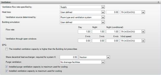
The ventilation flow rate can be specified for both the heat loss calculation and the building simulation. This is possible using multiple input methods and different units:
|
CL |
Natural ventilation for cooling load is an exception. This input can be specified in Infiltration > Cooling load.
|
HL BS
In this field it is
determined whether the flow rate is specified by supply or exhaust. For example,
habitable rooms need to be provided with fresh air, whereas the air should be
extracted in toilet compartments and bathrooms.
§ Supply, the ventilation flow rate is specified as supply
§ Exhaust, the ventilation flow rate is specified as exhaust
HL
§ According to building decree: the ventilation flow rate is determined automatically based on the utility function and room type as specified below Use > Room usage. The corresponding ventilation flow rate is taken from the table Ventilation flow in the Dutch Building Code.
§ More ambitious than building decree [Factor]: the ventilation flow rate is determined automatically from Use > Room usage. The corresponding ventilation flow rate is taken from the table Ventilation flow in the Dutch Building Code. This flow rate is then multiplied by the specified multiplication factor.
§ User defined [Select units *]: the ventilation flow rate is specified manually.
1/h, dm³/s, m³/s, m³/h, m³/(s.person), m³/(h.person), m³/(s.m² floor), m³/(h.m² floor), m³/(s.m² facade), m³/(h.m² facade), m³/(s.m² outside surface), m³/(h.m² outside surface). If the input is given per m² floor, the calculations are performed using fixed wall dimension, i.e. direct measures excluding wall thicknesses.. See Dimensions.
|
HL |
Dutch Building Code 2003, Section 3.10.1, Article 3:46 & Table 3.46.1 Ventilation of a residential area, lounge, toilet and bath room |
|
HL, WB |
ISSO Publication 51 (2009), section 4.3.2 Ventilation Heat Φvent
|
|
HL, UB |
ISSO Publication 53 (2010), section 4.3.2 Ventilation Heat Φvent
|
|
HL, UB |
ISSO Publication 53 (2010), Annex H Standard values for ventilation of various utility buildings
|
|
HL, UB |
ISSO Publication 53 (2010), section 3.3.2 Ventilation Heat Φvent
|
HL
The software attempts
to determine where the air originates as well as possible. For this purpose, you
can specify how the ventilation source is determined:
§ Room type and ventilation system; The software determines the origin of the air based on the Room type as defined in the template Use, and the selected in the HVAC template;
§ Room properties: the ventilation balance can be specified manually atAir Exchange and Ventilation Balance below room properties.
Ventilation system choice:
In case of ventilation systems
with natural supply of ventilation air, the outside air is used in the
calculations for habitable rooms and spaces.
•In mechanical supply, the air of the system is used in the calculations;
•In natural supply the outside air is used in the calculations (irrespective of the presence or absence of mechanical exhaust), unless an interior room is considered. In the latter case, the air is extracted from an adjacent room.
•In other rooms, the air from adjacent rooms is used in the calculations by default.
Note that the software will not execute these choices well in all cases; therefore, a thorough verification on its performance is recommended. Additionally, the software will not make a ventilation balance of the surcharged air. The choice of room type and ventilation system is used to perform a ventilation calculation quickly and automatically using the minimum ventilation requirements and the user-defined flow rates. When choosing ‘room properties’, a balance can be made by indicating the amount of air which enters and/or leaves the room.
In Properties> Rooms> Ventilation Balance it can be indicated how much air enters from other rooms or from outside. The total amount of air is in balance at all times, i.e. the amount of air which enters the room is the same as the amount of air leaving the room. A correct balance can be made by specifying the right flow rates of ventilation air and the origin of the air.
BS
The ventilation
properties for the building simulation are specified for day, night, and night
(conditional). These correspond to the daytime operation and night time
operation as defined in Schedule of HVAC.
§ Custom value [select units *]: a ventilation flow rate is specified.
|
BS |
ISSO Publication 32 (2011), Section 4.2 Ventilation http://www.issodigitaal.nl/?action=login&externalaction=linkmanager&id=docs/publicatie/32/4.html/4.2 |
Depending on the wind [select units *] BS
This is the ventilation flow rate in case the
windows are fully open, which is defined for various wind speeds. This flow rate
is only included when the windows are open; it is not included if Building operation >Openable windows
> Windows
stay closed has been activated.
EPG
The actual
ventilation power which is to be installed can be applied in the EPG
calculation. By checking this box, the ventilation flow rate for the room can be
specified. If this option has been chosen in one of the rooms within a zone, the
specified ventilation power is summed for all rooms within the zone.
Additionally the true ventilation power is used in the calculations for the
ventilation system defined within the zone (and possibly in multiple zones). If
this box is not checked in any of the rooms within a zone of the ventilation
system, then the minimum ventilation requirements are used in the
calculations.
[Select units *] EPG
The actual ventilation power in the room within a
zone can be specified using multiple units. In the EPG calculation, the flow
rates are computed in dm3/s and displayed in the results.
[Number, choice] EPG
This field allows you to indicate what share of the
air is preheated using the heat recovery. It applies to housing and it is used
in the energy performance calculation EPG. The share can be specified as a
fraction, or based on the utility surface of the rooms (living room). This
fraction or utility surface does not hold per room, but rather for the complete
zone in which the room is located.
EPG
The purge facility
which is used in the building or part of the building can be indicated here. By
default, openable windows are assumed in housing, irrespective of the input for
the purge facility. If a purge facility is defined it is applied in the complete
system, potentially also in different zone.
EPG
This indicates the
installed ventilation capacity is used completely for cooling of the building.
In this case the cooling load for the building can be reduced.
EPG
This indicates the
installed purge ventilation capacity is used completely for cooling of the
building. In this case the cooling load for the building can be reduced.
*) 1/h, dm³/s, m³/s, m³/h, m³/(s.person), m³/(h.person), m³/(s.m² floor), m³/(h.m² floor), m³/(s.m² facade), m³/(h.m² facade), m³/(s.m² outside surface), m³/(h.m² outside surface). If the input is given per m² floor, the calculations are performed using fixed wall dimension, i.e. direct measures excluding wall thicknesses.. See Dimensions.


