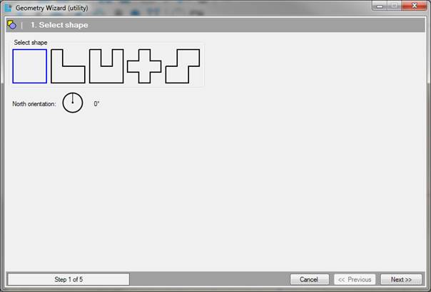
The first step is to choose a type of basic form for the
typical plan. It may be:
•A rectangular or square plan;
•An L-shaped plan;
•A U-shaped plan;
•An X-shaped or cross-shaped floor plan;
•A map consisting of two coupled rectangular or square shapes.
The dimensions of the buildings are not determined yet, and are adjusted in the next step of the wizard. Initially, the sides of the basic shapes all meet at right angles, these angles can be later in the drawing screen. Also, after the geometry wizard other abnormalities can be adjusted, such as voids, oblique and/or tilting walls, windows, doors, elevator shafts, etc.
[Degrees]
This option
sets the orientation of the model relative to the north line. Depending on the
setting chosen in this control the yellow north line in the geometry screen will
be rotated. The orientation of the building can be further refined by using the
Orientation control in
the geometry options.
•You can exit the wizard at any time by clicking. Cancel. The Wizard will then be closed, and any data entered into it will be lost.
•If the above information is entered correctly, go to Step 2 of 5; Measurements and floors by clicking on next.