Using a 2D CAD drawing the plan of a building (layouts of all
floors, windows and doors and the room names) are transferred to the 3D geometry
of Vabi Elements.
There are important guidelines to follow for the CAD drawing
that is to be used in the import. These guidelines ensure that the CAD file will
be imported correctly.
Examples of appropriate CAD drawings can be found under
(Windows Explorer to copy):% ALLUSERSPROFILE%\Vabi\Elements\Examples\
|

|
Errors may arise during the
CAD import due to the construction layers (from the original, detailed
drawing) still being present in the drawing. To help avoid this problem
copy the required layers of the drawing to a new blank CAD file, and then
import this file into Elements
|
|
|
If many walls on adjacent
floors do not line up with each other Vabi Elements can be slowed
significantly both in the geometry drawing and during calculation. In some
cases this even causes instability and crashes. It is therefore
recommended to try to draw the wall lines such that they line up with each
other as much as possible.
|
In order to be able to read from a CAD file the layout of the
building, the CAD drawing should adhere to the following conditions:
•
A plan should be drawn of each building storey; each wall should be drawn
as a single line.
•
The wall lines should be drawn at the mid-point of the constructions.
•
A single storey should not be spread over multiple drawing layers;
•
The lines representing the walls must fit together seamlessly, without
any gaps left in the geometry
•
Lines which do not represent structural elements of the building should
be removed prior to CAD import.
•
A room may not entirely enclose another room (no, Room in room);
When the line segments in the CAD drawing are entered at a
large distance from the origin point there may be imported correctly. To solve
this it is necessary to move the origin point in the CAD file.
Windows and doors can be imported by creating a block in
AutoCAD. The block is used to indicate which wall the window or door is and what
the dimensions of the door or window frame should be. Element reads the
attributes of the blocks to determine the height of the window/door frame, and
the vertical offset (how far above ground level the window is located. The width
of the window/door is read from the width of the block drawn in the CAD file.
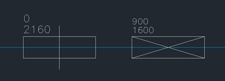
Figure13: Two predefined AutoCAD
blocks: a Door and a Window
•
Windows and doors are defined on a separate layer 0 (zero). Above the
block 2 attributes should be specified, the first is the height (HEIGHT) of the
window/door, the second attribute is the offset (OFFSET) which specifies the
height above the ground level.
•
The Insertion Point should be specified in the centre of the
rectangle
•
The content (figure) of the block does not play a role;
•
The name of a block can be chosen freely;
•
The name of an attribute can be chosen freely;
•
The block is then placed in the correct drawing layer on the appropriate
wall. The point of application of the block should be on the wall;
Elements will automatically assign room names in the order
they are imported into the program. It is however also possible to import the
room names from the CAD drawing.
•
The location of the origin of the text (Insertion Point, or base point)
must be within the appropriate room;
•
The names of the rooms may be on the same drawing layer as the drawn
areas. The room names can also be specified as a separate drawing layer;
•
Currently, only Single Line Text is fully supported. Multiline Text is
also imported, but can contain unnecessary characters.
•
The text before the colon is imported as a room number (max. 5
characters);
•
The text after the colon is imported as the room name;
•
Text without a colon separator is imported as the room number, with the
room name left blank.
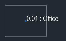
Figure14: Example of a proper
placement of a name label. The room in the example above would be imported as
room 0.01, with the name ‘Office’.
For a room-in-room inside another room, a specific drawing
technique should be used. This is because it is not possible to make a hole in a
plane in the geometry model that Elements uses.
|

Figure15: ERROR, a room-in-room according to the
above map cannot be imported and will not be counted. One should add at
least two guides |

Figure16: ERROR, a room in room with a single guide
cannot be imported and will not be counted. One should add an additional
guide. |

Figure17: GOOD, a room-in-room with two guides is
easily imported. |
This is defined as walls, which are drawn as (a part of) a
circle or ellipse or any other manner of a bend are provided. : The following
conditions apply
•
The entity must be an Arc. Spline and Circles are not (yet)
supported.
•
If the curved wall is only part of one room it can be imported directly
into Elements. The wall will be divided into facets, each at an angle of 15° to
the adjacent component.
•
If on the curved wall to connect one or more intermediate walls, so that
the curved wall is shared between multiple rooms it must be converted into wall
of straight line segments.