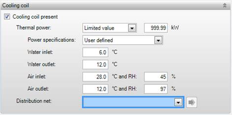
The coil specifications below should be entered according to the product data from the supplier. The screen above is the display for a cooling coil, but it is the same for the heating coil except for the relative humidity (RH).
HL BS PG
This indicates
whether a heating/cooling coil is present
•Unlimited; with this option it is assumed that the heating/cooling coil has unlimited power. Therefore, no maximum temperatures for the water supply and exhaust are applicable in this case;
•Limited value: the total thermal power should be specified here. This power should, at least, be consistent with flow rate as specified for the supply fan. Thus, the power of the coil as it is put in the air handling unit is concerned here.
|
In a building simulation the right amount of ventilation (for the rooms to be calculated) is used in the calculations by means of a fraction. This fraction for the cooling coil is determined from the fraction of the ventilation. The thermal power is determined at the water supply temperature, water exhaust temperature, air temperature, and relative humidity at the entrance and the exit which have been specified. If the thermal power is used only to realize the supply temperature, sufficient power should be available, i.e. 2 kW per 100 m³ air. In this case the default values for water supply- and exhaust temperature and air conditions can be applied without changing them. (Note that specifying a total power of 99,999 kW leads to a very large flow which can cause small inaccuracies.) |
BS
The type of temperature specifications can be
indicated here if the thermal power has a limited value:
•Vabi default: The default temperatures are applied, see table below;
•User defined: The temperatures can be specified manually.
|
|
Water supply |
Water drainage |
Air inlet |
Air output |
|
Warm |
70 °C |
-7 °C |
20 °C | |
|
Cool |
6 °C |
12 °C |
27.4 °C and 80% RH |
20 °C and 98% RH |
Standard 90 °C for heating and 6 °C
for cooling BS
This is the water supply temperature at which the thermal power
is computed, and it indicates the temperature of the supply water used for
cooling or heating. The water supply temperature used by the software for
calculations is determined by Temperatures of the linked Distribution resource.
Standard 70 °C in heating and 12 °C
for cooling BS
This is the water exhaust
temperature at which the thermal power is computed, and it indicates the
temperature of the exhaust water which remains after cooling or heating. This
temperature is used to compute the flow rate through the coil.
Standard -7 °C for heating and 27.4
°C for cooling BS
This is the air supply temperature at which the
maximum thermal power is determined. The air supply temperature is the outside
temperature in general, but in case of heat recovery / recirculation it is
computed by the building simulation.
[%] Standard 80% (only with cooling coil) BS
This is the relative humidity of the supply air. The
moisture conditions at the inlet are important as these conditions are mainly
responsible for determining the power, and consequently the efficiency of the
cooling coil when performing dehumidification.
Standard 20 °C for heating amen and
10 °C for cooling BS
This is the air
exhaust temperature at which the maximum thermal power is determined. Together
with the inlet temperature this is used to determine the air flow over the coil.
The building simulation performs its calculations using an air heating
curve.
[%] Standard 98% (only with cooling coil) BS
The moisture conditions at the inlet are important as
mainly these conditions determine the power, and consequently the efficiency of
the cooling coil in case of dehumidification.
|
|
Note: The above temperatures are the (maximum) power specifications of the cooling and/or heating coil. The actual temperatures (or heating curves) used in the calculations, are determined in the associated distribution network. |
[Selection] BS
The distribution network for this air handling unit
is selected here from the networks which have been defined within the current
project library. This distribution network is linked to a generation resource
and a generator which can deliver heat or cold to the coil.

