Heating the ventilation air from outside requires energy. A lot of this energy may be saved by adjusting the amount of supply air for ventilation to the need for ventilation. When applying heat recovery, the heat from the exhaust air is used to preheat the supply air. Heat recovery is only possible when both mechanical supply and mechanical exhaust are selected.
HL BS EPG
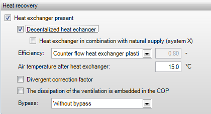
In this box it
can be specified whether heat recovery is present.
EPG
In this box it can be
specified whether decentralized heat recovery is present. Decentralized heat
recovery includes ClimaRad systems.
EPG
If a decentralized
heat recovery has been specified, in this box it can be indicated whether system
X is applied. System X can be used only in housing construction, i.e. the
computation of a non-residential building with system X is not
possible.
[%] HL BS EPG
The thermal, flat rate efficiency should be
indicated here. A choice should be made from the predefined types according to
NEN 7120.
|
|
NEN 7120
| |
|
HL |
ISSO Publication 51 & 53 (2009/2010), Annex C Calculation of the yield of heat
| |
|
Type of system |
Thermal efficiency |
Description |
|
Custom value |
|
The thermal (flat rate) efficiency may be specified manually. This value should be discussed for equivalence, and it should be rounded to a multiple of 0.05. |
|
Tube heat exchanger |
65% |
A tube heat exchanger (cross-flow heat exchanger or twin-coil heat exchanger) consists of flat and corrugated sheets of aluminium or stainless steel which have been manufactured alternately flat and corrugated. Supply- and exhaust air flows along these plates. The supply- and exhaust flows are strictly separated; therefore no moisture recovery from the supply air occurs. |
|
Twin-coil heat exchanger |
60% |
Twin Coil |
|
Cold storage with heat pump;
|
40% |
|
|
Heat pipe |
60% |
|
|
Rotating heat exchanger |
70% |
A rotating heat exchanger is a slowly rotating, intermittent heat exchanger made from small aluminium tubes. It is based on a heat-accumulating element in the shape of a wheel which is alternately run through supply and exhaust air. The thickness of the heat exchanger determines the heat capacity. The heat exchanger is rotating at a speed ranging from 1 to about 10 revolutions per minute. The temperature of the supply air can be kept reasonably constant by varying the angular velocity of the heat exchanger. The hot exhaust air is run through the aluminium tubes which take on the temperature of the exhaust air. The rotating wheel then runs the tubes through the supply air. This supply air is heated by the hot aluminium tubes. This same heat exchanger can be applied in offices with a cooling system to precool the hot supply air from outside using the relatively cool inside air during summer.
|
|
Counter flow heat exchanger |
75% |
A counter flow heat exchanger, or tilt valve system, consists of fans, a tilt valve, and two cassette cases with aluminium cassettes for heat storage. Air from the building is blown outside through a cassette box by means of a valve housing. The aluminium cassettes in the cassette case ensure that the heat from the suctioned air is stored in the cassettes. After a while the valve in the valve housing tilts, after which the cold outside air is led inside through the heated cassettes. The stored heat in these cassettes warms up the outside air. Efficiencies of 90% are possible with this system and also moisture recovery is a possibility. A combination is possible with adiabatic cooling, in which the temperature drops due to atomization. Besides heat recovery from hot ventilation air during winter, cold recovery in a cooled building is possible in the same way from the relative cold inside air during summer. |
|
Kantherm heat exchanger |
90% |
The Kantherm heat exchanger recovers heat, cold, and moisture from the exhaust air depending on the season. During winter the Kantherm recovers both heat and moisture, and in summer it can ventilate freely (free cooling) or recover cold. |
HL
The air temperature
after heat recovery is indicated here. This value is used in the heat loss
calculations. If only heat recovery is present in the system, this temperature
is blown into all rooms, unless heating by the ventilator is specified, which is
not included in the efficiency of the heat recovery. In the latter case the
heating of the ventilators is added to the temperature after heat
recovery.
EPG
By default, a
correction factor of 0.8 (practical efficiency correction) is applied on top of
the heat recovery efficiency. This correction accounts for air- or heat
leakages. In case you diverge from the standard correction factor of 0.8, this
should be supported by measurements or calculations according to NEN 8088,
Appendix C.
|
|
NEN 8088, Appendix C |
HL BS EPG
If the
dissipation of ventilation (heating of the ventilation air by the ventilator) is
included in the efficiency of the heat recovery, the specified heating of the
ventilator (if available) is not surcharged any more.
EPG
This option allows
you to specify whether the heat recovery uses a (partial) bypass. If this is the
case the cool outside air can cool the building during the summer months without
being post heated by the heat recovery. This will have a beneficial effect on
the EPC.
•Without bypass
•Partial bypass an additional input field appears in which the bypass share at cooling demand can be specified
•Full bypass

